Single Phase Motor Starter Circuit Diagram
This allows the motor to be started and stopped in stages, allowing for smooth acceleration and deceleration. Features , advantages/disadvantages & applications of dol starter what is direct online (dol) starter? The start and stop circuits could alternatively be controlled using a plc.
Wiring Diagram For Motor Starter Best Diagram Collection
Single Phase Motor Starter Circuit Diagram. Web a single phase motor starter wiring diagram provides an easy way to identify which wires need to be connected to the motor, helping to ensure each device operates correctly and safely. Once started the auxiliary winding is optional. Web bulletin 609 manual starters.
It Uses A Contactor, An Overload Relay, One Auxiliary Contact Block, A Normally Open Start Pushbutton, A Normally Closed Stop Pushbutton, And A Power Supply With A Fuse.
Because firing angle which is used to control thyristor operating angle is triggered at every zero crossing. Split phase or resistance start Split phase induction electric motor.
The Centrifugal Switch Is Used To Connect The Auxiliary Winding With The Capacitor And The Power Source.
5 thru 13 bulletin 509 magnetic full voltage starters. Dol starter (direct online starter) is. Dol ( direct online starter) star delta starter soft starter
Once It Is Moving, The Currents Induced In The Rotor Create A Magnetic Field That Interacts With The Pulsating Field To Produce A Torque, And Thus Rotation.
There are many variations for each type and further variations from one manufacturer to another. The start and stop circuits could alternatively be controlled using a plc. Loads must be connected in parallel when more than one load must be connected in the line diagram.
Electronic Starter For Single Phase Motor;
Web starting methods of single phase motor. Web software starter for single phase induction motor consists of following main components. Web i have a single phase electric motor provided with the following wiring diagram.
Once The Speed Reaches A Certain Value, The Switch Will Disconnect The Capacitor And The Auxiliary Winding From The Power Source.
The wiring diagram unfortunately omits the active line and neutral connection details. Web motor contactor (or “starter”) coils are typically designated by the letter “m” in ladder logic diagrams. Once started the auxiliary winding is optional.
“R” For “Run” And “S” For “Start”.
This circuit has two lines, one for the pilot light and one for the solenoid. Split phase or resistance start. Features , advantages/disadvantages & applications of dol starter what is direct online (dol) starter?
This Circuit Is Used To Detect Zero Crossing Signal Of Ac Power Supply.
The auxiliary winding of a permanent split capacitor motor has a capacitor in series with it during starting and running. When a capacitor is so introduced, the voltage lags the current by some phase angle. Web bulletin 609 manual starters.
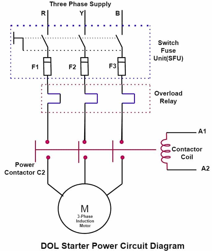
Web Single Phase Dol Starter Wiring Diagram:
Web split phase induction single phase motor diagram. Web dol starter control circuit diagram is also very important for understanding the working of dol starter. Split phase or resistance start;
You Only Need Two Contacts And One Resistor!
Types of starters for an induction motor there are three types of starters mainly used for starting a squirrel cage induction motor. The start winding can have a series capacitor and/or a centrifugal switch. This means there is no torque when the rotor is stationary.
Web Below Is The Single Phase Motor Centrifugal Switch Diagram.
It must be emphasized that the circuits presented are only representative. Zero crossing detector circuit : It has a starting winding of high resistance, which is physically displaced in the stator from the main winding.
I've Had A Look At Several Other Wiring Diagrams And Videos, But They Seem To Contradict Each Other.
The wiring diagram offers several other benefits as well. Web a single phase motor starter wiring diagram provides an easy way to identify which wires need to be connected to the motor, helping to ensure each device operates correctly and safely. Web the voltage from l1 and l2 appears across each load for the proper operation of the pilot light and solenoid.
This Allows The Motor To Be Started And Stopped In Stages, Allowing For Smooth Acceleration And Deceleration.

Direct Online Starter (DOL Motor Starter) Circuit Diagram and Working

Wiring Diagram For Motor Starter Best Diagram Collection

Single Phase Motor Starter Wiring Diagram Database Wiring Diagram

DOL Starter connection Single Phase Motor Connection with
Dol Motor Starter Wiring Diagram Pdf Wiring Diagram

DOL Starter Wiring Diagram (Direct Online Starter)

220V Single Phase Motor Wiring Diagram Cadician's Blog

Single Phase Motor Wiring Diagram Pdf Wiring Diagram
